Table of Contents
Introduction
The Harmonized Landsat Sentinel-2 (HLS) project provides consistent surface reflectance (SR) data from the Operational Land Imager (OLI) aboard the joint NASA/USGS Landsat 8 and Landsat 9 satellites and the Multi-Spectral Instrument (MSI) aboard Europe’s Copernicus Sentinel-2A and Sentinel-2B satellites. The combined measurement enables global observations of the land every 2–3 days at 30 meter (m) spatial resolution. The HLSS30 and HLSL30 products are gridded to the same resolution and Military Grid Reference System (MGRS) tiling and are “stackable” for time series analysis.
HLS Naming Conventions
HLS filenames (i.e., the local granule ID) follow a naming convention that gives useful information regarding the specific product.
In this example of a swath product, the filename HLS.S30.T60HTE.2022103T222539.v2.0.B01.tif indicates:
- HLS.S30 – Product Short Name
- T60HTE– MGRS Tile ID (T+5-digits)
- 2022103– Julian Date of Acquisition (YYYYDDD)
- T222539– Time of Acquisition (HHMMSS)
- v2.0 – Collection Version
- B01 – Spectral Band, Angle Band or QA(Fmask)
- tif – Data Format (Cloud Optimized GeoTiff)
The HLS Long Name (i.e., Collection-Level) convention also provides useful information regarding the product.
In this example for an HLSS30 dataset, all products belonging to the HLS Sentinel-2 Multi-Spectral Instrument Surface Reflectance Daily Global 30 m V 2.0 collection have the following characteristics:
- Sentinel-2 Multi-Spectral Instrument – Instrument/Sensor
- Surface Reflectance – Geophysical Parameter
- Daily – Temporal Resolution
- Global – Global or Swath
- 30 m – Spatial Resolution
- V 2.0 – Collection Version
HLS Temporal and Spatial Resolution
HLS Temporal Resolution
The HLS project is a NASA initiative to produce a Virtual Constellation of surface reflectance (SR) data from the Operational Land Imager (OLI) and Multi-Spectral Instrument (MSI) aboard the Landsat 8/9 and Sentinel-2 remote sensing satellites, respectively. The combined measurement enables global observations of the land every 2–3 days.
HLS Spatial Resolution
The combined measurements allow for observations at a moderate spatial resolution of 30 m for both the HLSS30 and HLSL30 products.
HLS Tiling System
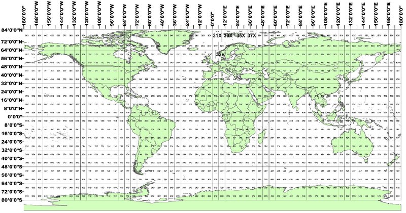
The HLS tiling system is identical to the one used for Sentinel-2. The tiles’ dimensions are 109.8 km squares with an overlap of 4,900 m on each side. The system is aligned with the Military Grid Reference System (MGRS), and its naming convention is derived from the UTM (Universal Transverse Mercator) system. The UTM system divides the Earth’s surface into 60 vertical zones. Each UTM zone has a vertical width of 6° of longitude and horizontal width of 8° of latitude, as shown in the map below. Each UTM zone is subdivided into MGRS 110 x 110 km zones.
HLS Data Processing
HLS uses a processing chain involving several separate radiometric and geometric adjustments, with a goal of eliminating differences in retrieved surface reflectance arising solely from differences in instrumentation. Input data products from Landsat 8/9 (Collection 2 Level 1T top-of-atmosphere reflectance or top-of-atmosphere apparent temperature) and Sentinel-2 (L1C top-of-atmosphere reflectance) are ingested for HLS processing. A series of radiometric and geometric corrections are applied to convert data to surface reflectance, adjust for BRDF differences, and adjust for spectral bandpass differences.
Three types of products are then generated: “S10” products – atmospherically corrected Sentinel-2 images in their native resolution and geometry; and the harmonized products “HLSS30” and “HLSL30.” These products have been radiometrically harmonized to the maximum extent and then gridded to a common 30-meter UTM basis using the Sentinel-2 tile system. Note that S10 products are not normally archived. The S30 and L30 products are resampled as needed to a common 30-meter resolution UTM projection and tiled using the Sentinel-2 Military Grid Reference System (MGRS) UTM grid.
A detailed description of methods applied for processing and harmonizing Landsat 8/9 and Sentinel-2 data is described in the table below:
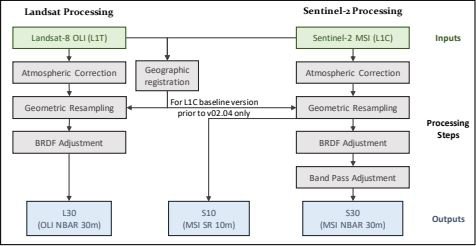
LP DAAC distributes both the L30 and S30 products:
- S30: MSI harmonized surface reflectance resampled to 30 m into the Sentinel-2 tiling system and adjusted to Landsat 8/9 spectral response function.
- L30: OLI harmonized surface reflectance and Top-of-Atmosphere (TOA) brightness temperature resampled to 30 m into the Sentinel-2 tiling system.
HLS Spectral Bands
| HLS Band Code Name L30 | HLS Band Code Name S30 | OLI Band Number | MSI Band Number | Wavelength (micrometers) | Band |
|---|---|---|---|---|---|
| band01 | B01 | 1 | 1 | 0.43 – 0.45 | Coastal Aerosol |
| band02 | B02 | 2 | 2 | 0.45 – 0.51 | Blue |
| band03 | B03 | 3 | 3 | 0.53 – 0.59 | Green |
| band04 | B04 | 4 | 4 | 0.64 – 0.67 | Red |
| - | B05 | - | 5 | 0.69 – 0.71 | Red-Edge 1 |
| - | B06 | - | 6 | 0.73 – 0.75 | Red-Edge 2 |
| - | B07 | - | 7 | 0.77 – 0.79 | Red-Edge 3 |
| - | B08 | - | 8 | 0.78 – 0.88 | NIR Broad |
| band05 | B8A | 5 | 8A | 0.85 – 0.88 | NIR Narrow |
| band06 | B11 | 6 | 11 | 1.57 – 1.65 | SWIR 1 |
| band07 | B12 | 7 | 12 | 2.11 – 2.29 | SWIR 2 |
| - | B09 | - | 9 | 0.93 – 0.95 | Water Vapor |
| band09 | B10 | 9 | 10 | 1.36 – 1.38 | Cirrus |
| band10 | - | 10 | - | 10.60 – 11.19 | Thermal Infrared 1 |
| band11 | - | 11 | - | 11.50 – 12.51 | Thermal Infrared 2 |
HLS Metadata
HLS products have two sources of metadata: the embedded COG metadata, and the external ECS (generated by the EOSDIS Core System) metadata. The COG metadata contains valuable information, including global attributes and dataset specific attributes pertaining to the granule. The ECS .met file is the external metadata file in XML format, which is delivered to the user along with the HLS product. It provides a subset of the COG metadata. Key features of HLS metadata attributes include georeferencing information and spectral band and QA band attributes:
- The ULX represents the X-coordinate of the Upper-left corner of the Upper-left pixel.
- The ULY represents the Y-coordinate of the Upper-left corner of the Upper-left pixel.
- The NCOLS represents the number of columns.
- The NROWS represents the number of rows.
- The DATASTRIP_ID is the datastrip name in the SAFE (Sentinel Standard Archive Format for Europe) file for the HLSS30 product.
- The HORIZONTAL_CS_CODE is the projection code in EPSG format.
- The HORIZONTAL_CS_NAME is the projection name
HLS Tools and Services
Data are available through NASA Earthdata Search.
A Cloud Optimized GeoTIFF (COG) is a regular GeoTIFF file, aimed at being hosted on an HTTP file server, with an internal organization that enables more efficient workflows in the cloud.
Certain open source tools and proprietary tools are available for use with HLS COG products:
Open Source Tools
Proprietary Tools
Additional information on HLS products is available from the HLS product website.